Monday, October 12, 2020

Rotary encoder secret decoded ...

There are many pages that deal with rotary encoders in connection with Arduino. Numerous diagrams with square-wave signals are published and reports on a shift in the signals depending on the direction of rotation. All of this is correct. But I was often missing a small but important piece of information.

What exactly happens when the encoder is only rotated one stop point further?

Unfortunately, this is not understandable for me from the many technical descriptions.
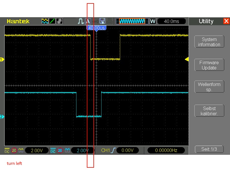
I couldn't explain it clearly to myself, so I just hooked up my own oscillograph. An example from the ardino accessories was used as an encoder. Pull-up resistors are already built in here.


I operated this with 5v and tapped the signals at CLK (yellow) and DT (blue). And now it looks very simple:

This is the information that I have always lacked in order to understand it:

The (my own) rotary encoder generates a complete single pulse on the CLK and DT, while the rotation continues by one detent point. In the idle state, both connections are at HIGH level. 

Depending on the direction of rotation, there is a time lag between the two signals. The trigger point would be the edge from HIGH (logic 1) to LOW (logic 0) at the CLK connection (or alternatively the rising edge). In order to determine the direction of rotation, you only have to determine the level at which the 2nd output is at this point in time. Exactly at this moment the level at the DT connection is always LOW when turning in one direction or always HIGH when turning in the other direction. I have framed this point in time in red in the screenshots of my oscilloscope.

Sunday, December 1, 2019

Universal ATmega 328p Board


Often there is a need for an Arduino project to control various power consumers. These can be low-voltage consumers, which should also be controlled with PWM. On the other hand, it can be about consumers who just want to turn on or off with relais. Of course, there are appropriate modules on the market that just need to be plugged. But when sensors and other modules are added, it gets confusing because of the many cables.
That's why I've developed a small PCB that contains some commonly used components, but also includes 2 power mosfets and 2 relays. As MCU serves the well-known ATmega 328p. The designation of the pins is Arduino Nano compatible. For a USB function you have to install the corresponding bootloader and connect a USB / TTL converter.
In the Arduino IDE the harddware must be adjusted accordingly on Arduino Nano.


The following features distinguish this board:
  • Buck Regulator with LM2596
  • Real time clock with DS3231
  • EEPROM socket
  • To control the buzzer and the relays the analog pins are used as output (A0, A1, A2)
  • 2 Power MOSFETs (FDD8447L) controlled via PWM connected to D9 and D10
  • The coil voltage of the relays can be 5V or the input voltage, selectable by jumper. If SSR is to be controlled you do not need to use relays and instead can solder a wire bridge to switch the SSR to the drive transistors of the relays)
  • Status LEDs for the relays, power transistors and alarm output of the DS3231
  • Additional connections for I2C and ICSP
  • EEPROM can be write protected via jumper


I originally designed this circuit to control my aquarium. The circuit can regulate the LED lighting via PWM with different lighting profiles. Furthermore, the temperature is controlled via relays and the CO2 system is switched. In addition, the water level is monitored and refilled with a small 12V pump if necessary. The sensor module contains a temperature sensor (DS18B20) which is cast in synthetic resin and a capacitive proximity sensor, which responds very well to the water surface.
However, I have not finished this project yet. I do not have a real idea for the case yet. It should not only be compact, but must also be overheating resistant and meet the necessary safety requirements for operation with 230V. Funny enough, I seem to need a lot more time for the case than for all the electronics. But that's exactly what I have not got at the moment because of my job. Not to mention that, for safety's sake, I have to take a multi-day test under supervision before I can run it self-sufficiently. And finally, the software is not finished yet. 95% of the MCU memory is already used up and I have to find optimization potential. ... That also led to the development of my "MightyNanoS", which can also be found on this blog. 

What works so far you can see in this video, but I did not connect the sensor assembly for this.

But why am I releasing an unfinished project? The answer is that during development I took care to keep it as universal as possible. So it is not a dedicated controller for an aquarium, but can be used in many fields. Just the currently much acclaimed home automation offers itself here, to name just one example.

My KiCAD project files can be downloaded from my Google Drive:
Google Drive
KiBoard_V2.3.zip
Bytes: 3905564
MD5: EFF29FD6D84D87A90EEA18ED76B6FD8F
SHA256: 285607216C3D8941B064AD230EE128B87AC86C69B0982ED9B892F85C83F2A788

There is another archive in the ZIP files. This can be uploaded directly to a board manufacturer (I use Seedstudio or JLCPCB) to order professional PCBs in your desired color.
My project is free for private use. It is aimed at experienced people. I take no guarantee! Duplication is at your own risk and responsibility!
You are welcome to customize or modify my project and publish it. However, you always have to refer to the origin!

Saturday, November 30, 2019

DIY GRBL 0.9+ board for Arduino Nano

I made a small laser cutter recently. This should be driven with an arduino nano. There are on eBay and other shops a "CNC Shield Version 4.0 Board". Hopefully I ordered several of these boards right away. But then came the bad surprise. All of these boards had errors and wrong connections. Without major alterations they were not up and running. That's why I've developed my own board for the Arduino Nano.


The designation of the connectors is grbl 0.9+ compatible. My board contains some more features. It is a buck regulator (MP1589) included, which ensures the power supply up to 24V input voltage. Thus, the stepper drivers can also be operated with this higher voltage, which may be useful in some circumstances. The diameter of the conductor tracks for the stepper drivers is sufficiently large, so that even higher currents can be used. In addition, the strong buck regulator also enables the supply of additional 5V consumers, such as sensors. The buck regulator and therefore the 5V technology is protected against reverse polarity of the input voltage by a power MOSFET.


You can see my machine powered by this board in this video.

There is another function. The enable signal of the stepper driver is used to control a fan. A fan for cooling the stepper driver can be connected to a small pin header. This fan must be a 5V fan or a fan suitable for the input voltage. This only runs if the stepper driver is active.


This project also includes a driving circuit for a laser. Here, too, I made bad experiences with the original circuits supplied and therefore developed my own circuit. Because lasers are very expensive and dangerous and do not forgive mistakes, only the experienced electronics technician should make a replica!

The driver circuit is a constant current source that can operate in PWM mode thanks to the high-speed optocoupler with up to 10 kHz. This circuit is suitable for laser diodes with currents up to 4.5 amperes. This laser driver purposely contains a slow dual OPA (LM358) because it provides a relatively clean output signal and it is frequency compensated for common mode. In addition, a time-delayed shutdown for the fan of the laser is realized with the second internal OPA from the LM358. The cooling of the laser starts when an input signal occurs and runs for another 30 seconds after the laser is switched off. 

However, what is additionally required is a good buck regulator, which provides the voltage required by the laser with sufficient power.


The output voltage of the buck regulators must be set to the maximum permissible voltage of the laser diode. This protects the diode and prevents overheating of the power MOSFET.

My KiCAD project files can be downloaded from my Google Drive
Google Drive

GRBL_V5.1 Board.zip
Bytes: 325107
MD5: 91B9ADBFE746B63C90AB36BA9C61E63C
SHA256: 2EAED850FB707BC1446D05051EEA5079F24879DAF73AB74D940CEB199D16B06F

Laserdriver.zip
Bytes: 249616
MD5: 2D7AEB7AF62058AF386E62074C359C56
SHA256: B427C313B893E182B4026F11F3932480043F2D06B0BB0B0D029E95F10FC63AC4

There is another archive in the ZIP files. This can be uploaded directly to a board manufacturer (I use Seedstudio or JLCPCB) to order professional PCBs in your desired color.
My project is free for private use. It is aimed at experienced people. I take no guarantee! Duplication is at your own risk and responsibility!
You are welcome to customize or modify my project and publish it. However, you always have to refer to the origin!